
Magnetic Force Microscopy (MFM)
MFM is a technique derived from AFM, in which an etched silicon cantilever/tip combined with optical deflection detection is used to precisely measure local forces such as those caused by van der Waals or Coulomb interaction. MFM uses cantilevers with very low spring constant K and with magnetic coatings (typically NiCr or cobalt), sensitive to the magnetic interaction between tip and sample.
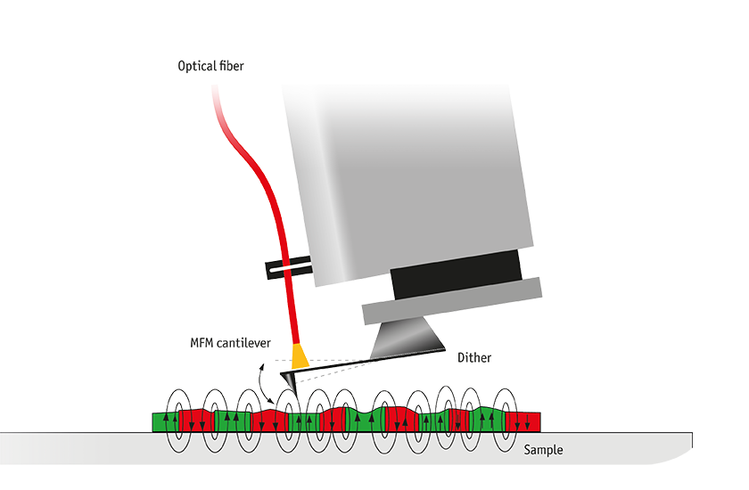
The figure below shows a schematic of attocube’s cantilever-based attoMFM, designed particularly for low temperature and high magnetic field applications. The attoMFM uses a single-mode, fiber-based interferometer to detect tip deflections with noise densities as low as 0.5 pm/Hz1/2. As with most MFMs, the attoMFM applies an AC modulation technique to achieve highest detection sensitivity. In AC mode, the cantilever is mechanically excited at its natural resonance frequency f0 using an oscillator swinging perpendicular to the sample surface. The magnetic interaction offsets the equilibrium position of the tip. This effect is hard to detect, and therefore ignored in most cases. In addition to the pure DC offset, the natural resonance frequency (as well as amplitude and phase) of the cantilever is also affected by the magnetic interaction. This frequency shift Δf = fres - f0 can be detected by classical lock-in techniques and is the most relevant physical quantity to measure due to its direct proportionality to the derivative of the local force F: ∂Fz /∂z ~ 2 K Δf / f0.
The measurement therefore yields information about the actual local magnetic stray field: ∂Fz /∂z ~ mtip,z ∂2Hz /∂z2 (where mtip,z is the magnetization of the tip perpendicular to the sample surface) with very high spatial resolution. Using a phase-locked loop (PLL) technique, resonance frequency shifts as small as 1 μHz can be detected. To separate magnetic information from other influences, two techniques are commonly used: constant height mode and constant distance mode. In constant height mode, the MFM tip is scanned at a fixed height above the mean sample plane. In constant distance mode on the other hand, the distance between tip and sample is kept precisely constant to compensate any surface corrugation. Constant height mode is typically applied on sufficiently flat samples, after the sample and scan planes have been aligned parallel to each other. The MFM tip is positioned at typically 10 – 100 nm above the sample surface, and is then scanned across the surface with scan speeds of up to several 10 μm/s. Any shifts in resonance frequency or phase are recorded simultaneously. Due to its ease of use and high scan speeds, this technique best fits a variety of samples such as hard discs and superconductors. In contrast, constant distance mode tracks the surface topography at a defined distance. This technique best suits samples with rough surfaces. However, this mode leads to considerably longer acquisition times than constant height mode.