

Technical Background for mK Setups
effects of resistive wiring, power dissipation, leakage currents
Unlike in 4K-cryostats, heating effects become a major issue when reaching mK temperatures. Main sources of heating caused by attocube positioners are: dissipating power from engaging the actuator, ohmic heating due to finite resistance of the piezoelement, and thermal connection to RT due to wiring.
Wiring of an attocube Piezo Positioner & Effects of Resisitive Wiring
The electrical signal applied to the piezo element consists of a slow rise and a steep drop (sawtooth signal). Increasing the resistance of the connected wire causes the sawtooth signal to smear out. A sharp transition is essential for the movement of the positioner.
In general, attocube suggests to use copper (typ. 0.7 Ω/m @ 0.2 mm diameter) or brass wiring (typ. 1.5 Ω/m @ 0.25 mm diameter) with a total resistance (both wires) of not more than 2 Ω (bandwidth 100 kHz). In this case, attocube fully guarantees the functionality and the specifications of the positioners. With a resistance of 2 - 5 Ω some specifications might be altered (e.g. max. load, min. step size, etc.) but the general functionality of the positioner is kept. If the resistance of the wires is between 5 and 10 Ω it is recommended to contact attocube.
Such wiring specifications are often in conflict with the requirements for mK setups because of the high specific heat values of the materials used. Therefore, for mK setups attocube uses a combination of copper wires and superconducting or phosphor-bronze wires.
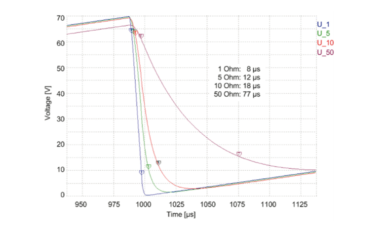 Shape of the steep flank of the sawtooth signal as a function of the total wire resistance.
To balance the thermal and the resistive load, copper wires are typically used from RT down to the 4 K stage or the 1 K pot. From there, either superconducting NiTi wires or phosphor-bronze wires lead to nanopositioners. Phosphor-bronze wires allow for the testing of the complete setup at RT, where superconducting wires have very high resistance.
attocube's strategic DR suppliers already offer standardized low-resistance cabling for attocube nanopositioners. Furthermore, in order to reduce the heat load on the sample stage, the total number of wires for nanopositioners, as well as for scanners, is reduced by using a shared ground.
Power Dissipation
The power dissipation of the capacitive piezoelement is another source of generated heat at ultra-low temperatures. A Piezo dissipates the power P = f CU² tanδ with the total power P, maximum voltage U, piezo capacitance C, signal repetition rate f, and loss angle δ of the dissipated electrical power.
For example, with C = 200 nF, f = 10 Hz, U = 70 V, and tanδ ≈ 4% the heat generated calculates to P = 490 μW. In case of a rotator, this number gets doubled because there are two piezoelements used to drive these positioner types.
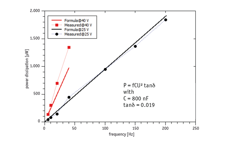 Comparison between calcuated and measured power dissipation.
Leakage Currents
Piezoelements typically have GΩ resistances. Even with e.g. 1 GΩ resistance, the heating due to leakage currents at 100 V static voltage is order of P = U²/R = 10 μW. This leakage current can only be reduced by using elements with higher ohmic resistances. attocube ensures a reduced leakage current by hand-selecting the piezoelements for dedicated mK positioners.