

IDS3010 Detecting Vibrations with Picometer Resolution
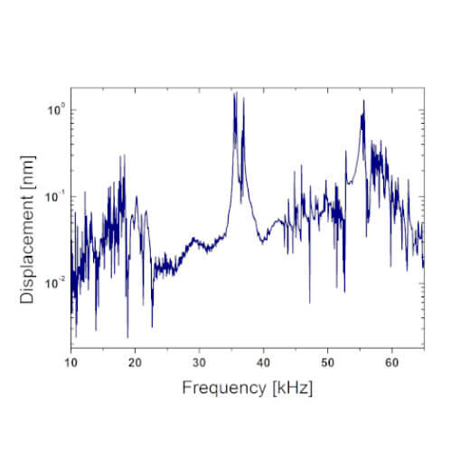
The renowned science journal “Nature" has recently published an article describing the experimental observations of a two-dimensional quantized quadrupole insulator. In these experiments, performed at the Institute for Theoretical Physics of the ETH Zürich, attocube's interferometer IDS3010 was used for vibration analysis of a mechanical metamaterial after exciting with an ultrasound air transducer.
The IDS3010 identified small vibrations at different locations of the mechanical metamaterial to identify the resonant frequencies. The small error estimate of 11.2 pm enables comprehensive results in the experimental analysis of phononic quadrupole topological insulators.
This measurement was realized with the Displacement Measuring Interferometer.
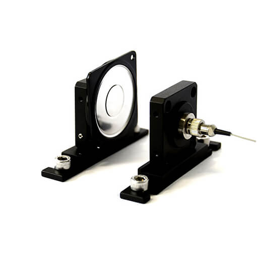
Measuring a speakers‘ frequency response using the interferometric sensor
Only recently, attocube released the new FPS3010, which is even more integrated and automated as previous versions. Here, the FPS3010 was used to measure the displacement of a speakers’ membrane to characterize its frequency response. The setup is shown in Figure 2.
The new FPS3010 has outstanding properties such as a measurement bandwidth of 10 MHz. At the same time, the alignment restrictions for the optical sensor are relaxed, due to a large acceptance angle of ±0.4°. This makes the FPS3010 usable in a wide range of applications. The standard version is equipped with three sensor channels for the detection of e.g. linear movement together with pitch and yaw or 3D motion.
This measurement was realized with the Displacement Measuring Interferometer.
Fiber based laser interferometry stimulating the development of highly precise micro manufacturing
Ultra-precise and contactless surface analyses are of major interest in order to guarantee the quality of the material in many research and industrial applications. The large acceptance angle is one of the main strong benefits of attocube’s Industrial Displacement Sensor (IDS). Due to its proprietary patented techniques, the system allows for measurements on surfaces with more than 10° inclination with respect to the measurement direction. The actual measurement shows nanometer precise 3D profilometry data of micron-sized metal cylinders. Several deformations can be seen: In the center position the object profile clearly shows a dent on its surface with a depth of around 400 nm. In addition the diameter contour in the front part near x = 0 has a plateau over a length of approximately 10 µm.
This measurement was realized with the Displacement Measuring Interferometer.
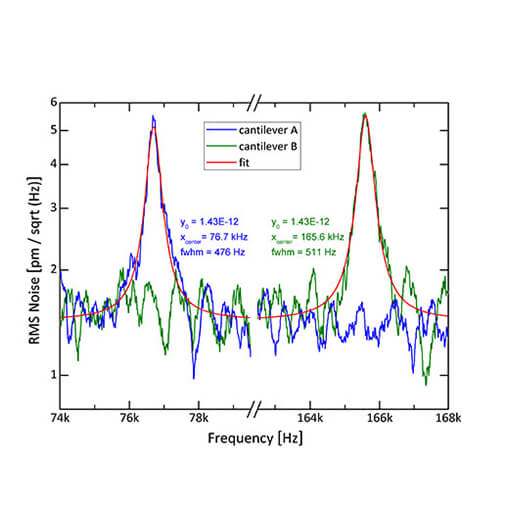
Measuring Brownian Motion of Comercial Micro-Cantilevers
Frequency analysis is a standard method to study demanding applications and measure the frequency dependent mechanical motion of e.g. micro- or nanomechanical systems (MEMS / NEMS). Measuring vibrations with amplitudes of only few picometers is very challenging, exceeding the capabilities of other commercially available measurement techniques.
To demonstrate that attocube’s fiber-based Displacement Sensor (IDS) not only has high-resolution but also a very low noise floor, we measured the resonant vibrations of micro-sized cantilevers which were excited only by their thermal energy at ambient conditions.
This measurement was realized with the Displacement Measuring Interferometer, and the .

Contactless Frequency Analysis of Motor Vibrations
Machine vibrations induce errors in parts manufacturing. The miniscule vibrations of a milling machine produce erratic motions of the workpiece with regards to the cutter and hence, may lead to contouring errors or a bad surface finish. Such defective parts create problems and can jeopardize the whole system’s assembly or safe operation. In the end, they may fail quality criterions such as the 6-sigma standard. Get our latest application note & see how the FPS3010 can help to efficiently and precisely characterize vibrations, thus helping to succesfully eliminate these errors.
This measurement was realized with the Displacement Measuring Interferometer.
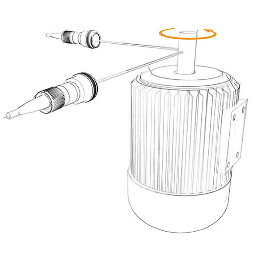
Ultra-precise contactless detection of bearing errors
To monitor the health status of a gear or machine, attocube’s IDS3010 can be used to track machine vibrations. To improve the vibration behavior of a machine, its motor was rotated at different speed levels and the motor’s vibrations were measured on the outer shell of the motor. Conducting a live Fast-Fourier-Transformation (FFT) showed that the motor rotating with 2000 rpm generated vibrations at 270 Hz which in turn amplified a system resonance at 345 Hz, and therefore drastically increased the overall vibration amplitude. At this system status, the vibrations amplitude was identified to be more than 150 nm, while the maximum acceptable amplitude was set to 100 nm. This crucial information enabled the system’s manufacturer to minimize the system response to vibrations and prevented potential failure.
This measurement was realized with the Displacement Measuring Interferometer.
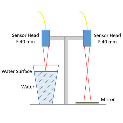
Displacement Measurement on a Water Surface
To measure the displacements of a cup’s water surface compared to the displacements of the table the cup is positioned on, two focused sensor heads were used: one of them focused on the water surface, the other focused on a mirror fixed to the table, while the table was hit by a hammer. The water surface oscillates with a maximum deflection of approximately ± 20 µm and the table oscillates with a maximum amplitude of around ± 0.7µm. The zoom highlights that the two measurement arms show similar behaviors in the high frequency range for the first milliseconds after the excitation.
This measurement was realized with the Displacement Measuring Interferometer.
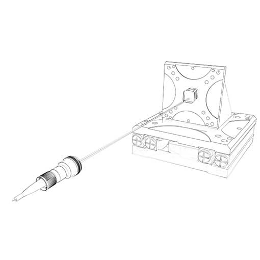
Optical Interferometer in Quality Control of a Nanopositioner
We've combined two of our products to ensure the highest quality delivered to our customers: In this application note we show the implementation of the FPS3010 interferometer in the quality control process of our nano drives. The outstanding precision of the FPSensor will ensure that every positioner delivered fulfills the highest quality standards, whereas the easy & robust alignment of the sensor permits high throughput, and therefore reduced lead-time.
This measurement was realized with the Displacement Measuring Interferometer.
Detecting vibration propagation and parasitic motions with picometer resolution
Exact sample positioning in synchrotron beamlines requires position detection with highest resolution. A group at the Diamond Light Source designed a sample positioning system with three positioners for x, y, z movements. To determine the error motions, eight axes of three IDS3010 devices were triggered for synchronous data acquisition, controlling the movement with BiSS-C interface. They identified parasitic motions of only 100 pm that were caused in the non orthogonal fixing of the positioners. These smallest amount of deviation can be detected in Ultra-high vacuum only - and with the IDS3010.
(Trevor Bates, Brian Nutter, Diamond Light Source Limited, Oxfordshire, England)
This measurement was realized with the ECSx5050/Al/RT, and the Displacement Measuring Interferometer.
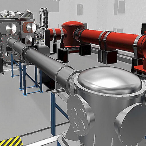
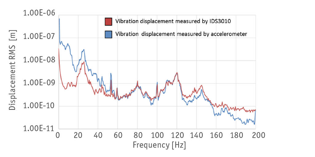
Vibration of high-power precision laser mirror
At the “ELI Beamlines facility”, currently under construction in Dolní Brežany close to Prague in the Czech Republic, we have developed an ultra-high pointing stability laser mirror mount for guiding the world’s highest repetition rate HAPLS Petawatt laser over up to 107 meters onto the target. The attocube IDS3010 offers major advantages compared to standard sensors like capacitive probes and accelerators when measuring 5 - 100 nrad RMS pointing stability of a mounted high-power precision laser mirror. While accelerometers may be used to measure mirror dummies for frequencies >≈12 Hz, the IDS3010 interferometer may diagnose contactless sub-nm displacements up to 10 MHz of mounted mirrors without risking the degradation of its laser damage threshold. In addition the IDS3010 sensor allows working distances up to a few meters. The software WAVE has proved to be convenient for visualizing in real-time the displacement data and for identifying resonant frequencies.
(Dr. Tomas Laštovicka, Dr. Martin Sokol, Dr. Michael Morrissey, Ing. Antonin Fajstavr, Dr. Stefan Borneis ELI-Beamlines, Dolní Brežany, CZ)
This measurement was realized with the Displacement Measuring Interferometer.
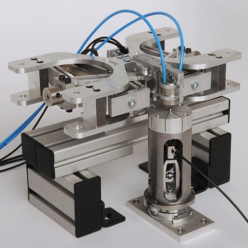
Interferometric Multi-Axis Motion Control of an X-Ray Setup
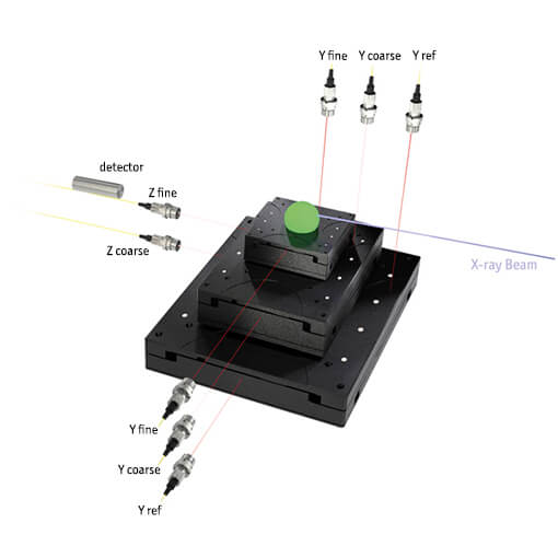
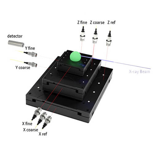
In high precision systems for moving objects in nanometer ranges, error motions and vibration propagation are crucial information for the motion accuracy. Due to this, synchrotron facilities continue to develop and upgrade different components to keep pace with the latest available technologies. The beamline I08 recently upgraded the end-station using attocube interferometers IDS3010 with BiSS-C interface. An experimental setup at the Diamond Light Source is synchronously triggering and tracking the movement of eight different linear axes. These eight axes were controlled by the Delta Tau “GeoBrick” controller, which ensures the accurate timestamped data from all eight axes, i.e. three IDS3010 devices.
The setup consists of three motion modules as shown in a simplified version in the upper figure: from the bottom one manual positioner, on top of it one stepper motor for more coarse adjustments, and finally on top of that one piezo-based positioner for fine motions. All three modules can move in X-, Y-, and Z-direction, i.e. the complete setup consists of 9 linear movements, and is being tracked by 8-axes consisting of M12/C1.6 high vacuum compatible sensor heads. Since the sample’s position is relevant for each movement of the three modules, every motion axis needs to be tracked. There are two kinds of error motions (parasitic movements) relevant for the sample’s position: vibrations caused by moving the positioner that spread to connecting positioners and the sample, as well as uneven motions caused by non-parallel mountings between the positioners.
One measurement example is shown in the lower figuer, which only involves the X, Y, and Z piezo-based positioners in the upper module. The two parasitic movements are shown while moving the fine piezo positioner in the X-direction using 5 nm step sizes. The red line (X-axis) shows the positioner moving in one direction, after 10 steps, the positioner is moving back with one 50 nm step. The blue line (Y-axis) shows the error motions of the fine positioner orthogonal to the motion of the positioner in the horizontal level. The noised oscillations are caused by vibration propagation emerging from the positioner’s motions. This line shows a linear offset of 10 pm for every step. This offset originates from the not perfect parallel mounting between the X- and Y- positioners. This non orthogonal mount can be compensated using the information for the other axes. The green line (Z-axis) shows the vertical movements of the fine positioner. Only the last step of 50 nm shows a significant change of the vertical position, presumable due to a rapid vibration.
(Diamond Light Source Limited, 2017)
This measurement was realized with the Displacement Measuring Interferometer.
Ultra-wide frequency range vibrometry
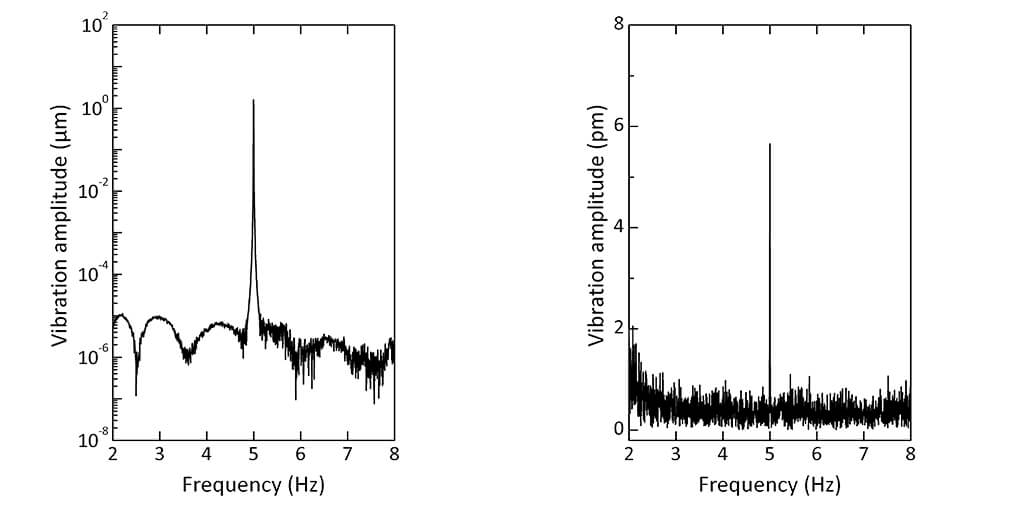
The FPS sensor is not only a very capable real-time displacement sensor but it also serves the user as a powerful vibrometer. With its built-in fast-Fourier algorithm (FFT), the FPS series directly detects the distribution of vibrational modes/amplitudes in frequency space. Frequency and phase information of resonance peaks can be live-viewed on the PC-based FPS application software. The data above demonstrate the suitability of the FPS sensor for this type of application. In this specific case, the low-frequency noise behaviour of the FPS sensor was tested by exciting and measuring the vibration spectrum of a ceramic piezo at low frequency and ultra-low amplitude. As can be seen from the data, the noise floor of the measurement is at 1E-6 µm equivalent to 1 picometer. Stunningly, this noise floor extends to very low frequency, enabling picometer resolution at frequencies as low as 2 Hz. Data are recorded at 100 Hz bandwidth.
(attocube applications labs, 2014)
This measurement was realized with the Displacement Measuring Interferometer.
Long distance and high-speed displacement measurements
Machine vibrations induce errors in parts manufacturing. The miniscule vibrations of a milling machine produce erratic motions of the workpiece with regards to the cutter and hence, may lead to contouring errors or a bad surface finish. Such defective parts create problems and can jeopardize the whole system’s assembly or safe operation. In the end, they may fail quality criterions such as the 6-σ standard. Get our latest application note & see how the FPS3010 can help to efficiently and precisely characterize vibrations, thus helping to succesfully eliminate these errors.
This measurement was realized with the Displacement Measuring Interferometer.